Raised-Cosine filters are commonly used in digital data communication systems to limit Intersymbol Interference (ISI). The Impulse Response of a Raised-Cosine filter is zero at each adjacent symbol period. In this example, we use ScopeFIR™ to design a Raised Cosine FIR Filter.
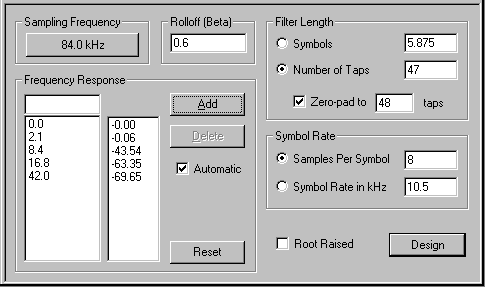
Specifying a Raised-Cosine filter is straight-forward, and requires only the “rolloff factor” (often called “beta” or “alpha”), the sample rate, the symbol rate, and the number of FIR taps. ScopeFIR’s Raised-Cosine Specification Editor is shown below for an example which has a rolloff factor of 0.6, a sampling frequency of 84 kHz, 8 samples per symbol (for a symbol rate of 10.5 kHz), and 48 total taps:

As its “Root Raised” option suggests, ScopeFIR can also design “Root-Raised-Cosine” filters (although we did not select that option in this example.) “Root-Raised-Cosine” filters are used in cases where the overall Raised-Cosine response is split equally between the transmitter and the receiver. These filters are “root” (square root) in terms of the Frequency Domain. Since the frequency response of the transmit and receive filters will be multiplied together at the receiver, the receiver will see a signal which has been filtered by a (plain) Raised-Cosine filter overall if we use Root-Raised-Cosine filters in both the transmitter and receiver. Since the “root” is in the Frequency domain, not in the Time domain you cannot simply take the square root of the Impulse Response of a Raised-Cosine filter to design a Root Raised-Cosine filter; the only way to design Root Raised filters is to calculate the square root of the Raised-Cosine Filter’s Frequency Response, then transform it to the Time Domain to create the filter’s Impulse Response (which, for a FIR filter, is the same thing as the coefficients). This procedure is somewhat complicated to do manually, but if you select the “Root Raised” option, ScopeFIR does it all for you automatically.
Along with specifications, the Raised Cosine Specification Editor displays some useful information. Although we had entered the symbol rate in terms of “samples per symbol”, ScopeFIR automatically calculated the equivalent symbol rate. It shows that the length of the filter corresponds to 5.875 symbols, and it shows the filter’s Frequency Response (in terms of dB) at frequencies of zero, half the sampling rate, and at the two Raised Cosine corner frequencies (in this case 2.1 and 8.4 kHz), as well as at twice the second corner frequency (16.8 kHz).
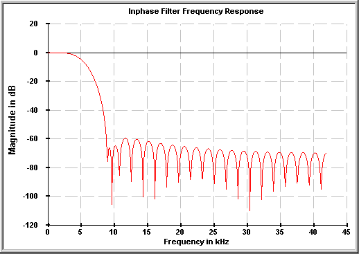
Having designed the filter, ScopeFIR shows the Frequency Response and Impulse Response plots. Here is the Frequency Response:

As expected, this plot has the “Raised-Cosine” shape. It is flat at low frequencies, then tapers off in a “cosine” shape toward the stopband. A theoretical Raised Cosine filter has infinite attenuation in the stopband, but in this case we see a limited stopband attenuation of about 60-70 dB. This is due to the number of filter taps we chose (47); we could have used more taps if more attenuation was desired, but that would have resulted in more calculations and more delay through the filter; in this application, 47 taps was deemed to be a good compromise.
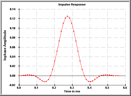
The Impulse Response plot below displays the feature required to achieve zero Intersymbol Interference:

Starting from the center (peak) tap, we can see that the Impulse Response passes through zero at each interval of eight taps. (The design specification above gave eight samples per symbol, so each set of eight taps corresponds to one sample period.) Note, however, that if we do not “synchronize” our symbol sampling to the right instant (which is the center tap of the filter) we will begin to have Intersymbol Interference. For example, if you start just one tap off from the center, then look at the response of the filter eight taps away from that, you will see that the Impulse Response has a non-zero value. This illustrates that even with the correct filter, Intersymbol Interference can occur if the symbol sampling synchronization is not correct.
In this case, we have designed our Raised Cosine filter to have 47 taps, but we then zero-padded it to 48 taps. Why? Well, by using an odd number of taps, the center of the Impulse Response is a peak (rather than two equal values). This peak helps us with the data synchronization. So why pad it to 48 taps? The answer is that we would like to be able to decimate or interpolate by the number of samples per symbol (in this case, 8). An efficient implementation of decimation or interpolation requires that the number of FIR taps be a multiple of the decimation or interpolation factor. Therefore, we zero-pad our 47-tap filter to 48 taps, because 48 is a multiple of 8. Even though the zero-pad tap isn’t really doing any “filtering”, it allows us to efficiently decimate or interpolate our receive or transmit Raised Cosine filter by factors of 8 (or even factors of 4 or 2).